Marine Switch Diagram 4 Gang Rocker Panel
Hey friend, let's dive into the world of marine wiring diagrams, specifically focusing on the keyword "marine switch wiring diagrams." We will explore different types of marine switches and learn how to wire them properly on your boat for a smooth sailing experience. So, grab a cup of coffee, sit back, and let's get started!
4 Gang Switch Panel Wiring Diagram
First up, we have the 4 gang switch panel wiring diagram. Switch panels are common onboard boats and provide an organized way to control various electrical devices. In this diagram, we can see how the switches are connected to control different circuits. It is essential to wire the switches correctly to ensure safety and functionality. Consult the diagram below to understand the wiring connections:

To wire a 4 gang switch panel, you will need to follow a few steps. First, determine the power source for the panel. Usually, the power comes from the boat's battery through a fuse. Next, identify the different circuits you want to control with each switch. Connect the positive terminal of the circuit to the switch and the negative terminal to the boat's common ground. Repeat this process for each switch and circuit, ensuring proper insulation and secure connections.
Remember to label each switch with its corresponding circuit for easy identification. This wiring diagram serves as a visual guide to assist you in properly wiring your boat's 4 gang switch panel.
Rv Battery Isolator Wiring Diagram
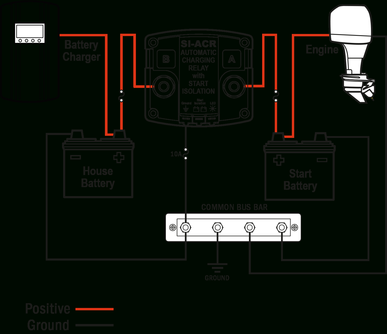
Next, let's explore the wiring diagram for an RV battery isolator. An RV battery isolator is a device that allows multiple batteries to be charged simultaneously while preventing discharging between them. This diagram shows you how to wire your battery isolator correctly:
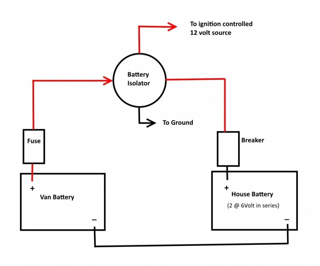
To wire an RV battery isolator, you will need to connect the positive terminals of all the batteries together. Then, connect the isolator to the positive terminals and the boat's common ground. This setup ensures that each battery is charged simultaneously and prevents power drainage between batteries. Follow the diagram above for a clear understanding of the wiring connections and ensure a reliable power supply for your RV.
Using an RV battery isolator is crucial to maintain a steady power source and prevent any electrical issues while on the road. Make sure to follow the manufacturer's instructions and consult a professional if needed.
Carling Switches Wiring Diagram
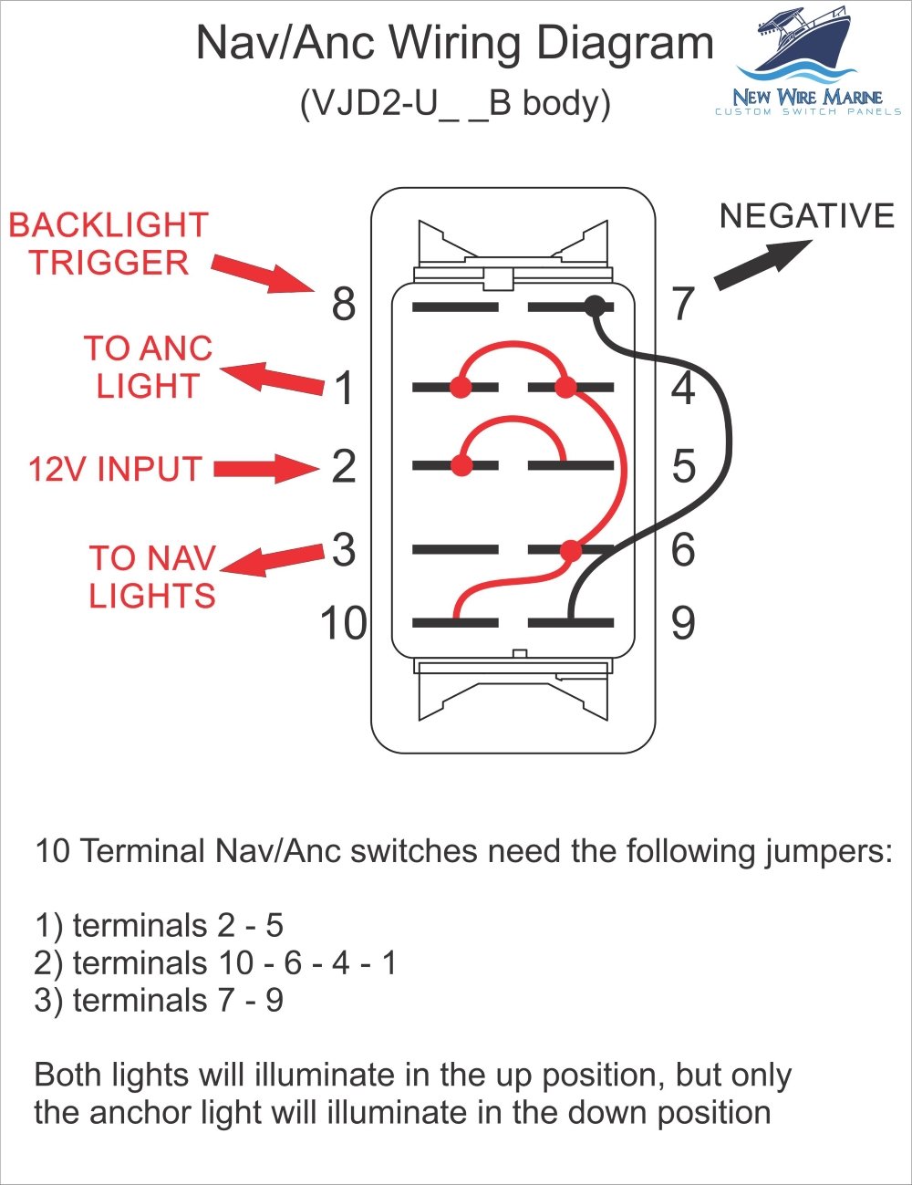
Moving on to Carling switches, which are known for their durability and reliability. This wiring diagram demonstrates how you can wire Carling switches in your marine applications:
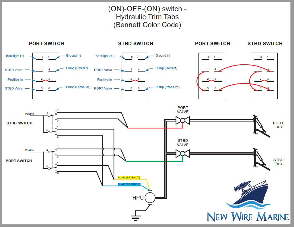
Carling switches are widely used in marine electronics due to their robust construction and versatile functionality. To wire a Carling switch, you need to identify the switch terminals, which include the power or battery supply, load output, and ground. Connect the power supply wire to the appropriate terminal, then wire the load output to the desired device or circuit. Finally, connect the ground wire to the switch's ground terminal. This diagram will guide you through the process and help you achieve a professional and secure wiring connection.
Always ensure that you use the correct gauge wire and appropriate connections to handle the expected current. This will ensure the longevity and safety of your marine electrical system.
Bep Marine Battery Switch Wiring Diagram
Let's now focus on the wiring diagram for a Bep marine battery switch. A battery switch allows you to control the electrical power flow in your boat and manage the battery's charge. The following diagram illustrates the correct wiring for a Bep marine battery switch:

To wire a Bep marine battery switch, you need to connect the positive terminal of the battery to the switch's common terminal. Then, connect the positive output terminals of the switch to their respective loads or circuits. Remember to connect the negative terminal of the battery to the boat's common ground. This wiring setup allows you to control the power supply to different devices or circuits by simply manipulating the switch. The diagram above highlights the correct connections for a Bep marine battery switch.
Properly wiring your marine battery switch ensures efficient use of power and prevents unnecessary drainage when not in use. It also adds an additional layer of safety to your boat's electrical system.
Boat Battery Selector Switch Wiring Diagram
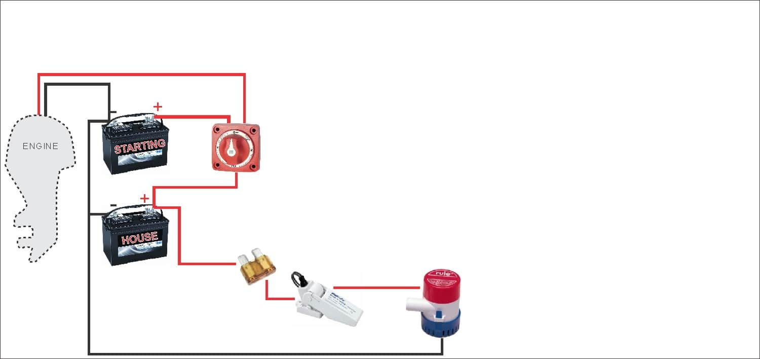
Moving on, we have the boat battery selector switch wiring diagram. A battery selector switch allows you to choose between different batteries or combine them for increased power capacity. Take a look at the following diagram to understand how to wire a boat battery selector switch correctly:
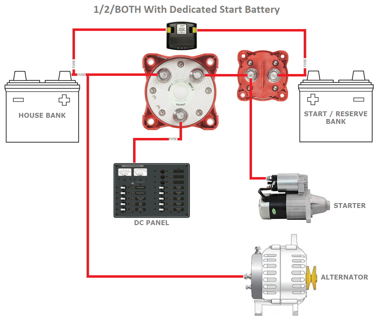
To wire a boat battery selector switch, start by identifying the switch terminals labeled as Battery 1, Battery 2, and Common. Connect the positive terminals of the batteries to the corresponding switch terminals, ensuring proper insulation and secure connections. Then, connect the boat's common ground to the Common terminal of the switch. This setup allows you to choose between individual batteries or combine them in parallel, depending on your power requirements. The provided diagram offers a clear guideline for wiring a boat battery selector switch.
Remember to follow the manufacturer's instructions and consult an expert if you are unsure about the wiring process. Safety should always be a priority when working with marine electrical systems.
Perko Marine Battery Switch Wiring Diagram
Next, let's talk about the wiring diagram for a Perko marine battery switch. Perko switches are renowned for their quality and reliability in the marine industry. This diagram will guide you in correctly wiring a Perko marine battery switch:

Wiring a Perko marine battery switch requires identifying the switch's different terminals, which include Battery 1, Battery 2, and Common. Connect the positive terminals of the batteries to the corresponding switch terminals, ensuring secure connections. Then, connect the boat's common ground to the Common terminal of the switch. This setup allows you to select individual batteries or combine them based on your power requirements. Refer to the diagram above for a better understanding of how to wire a Perko marine battery switch.
As always, take necessary safety precautions and follow best practices when working with electrical systems on your boat. Consult a professional if you have any doubts or questions regarding the wiring process.
Marine Ignition Switch Wiring Diagram
Now, let's explore the marine ignition switch wiring diagram. The ignition switch is a crucial component for starting and stopping the engine on a boat. Here's a diagram illustrating the correct wiring for a marine ignition switch:
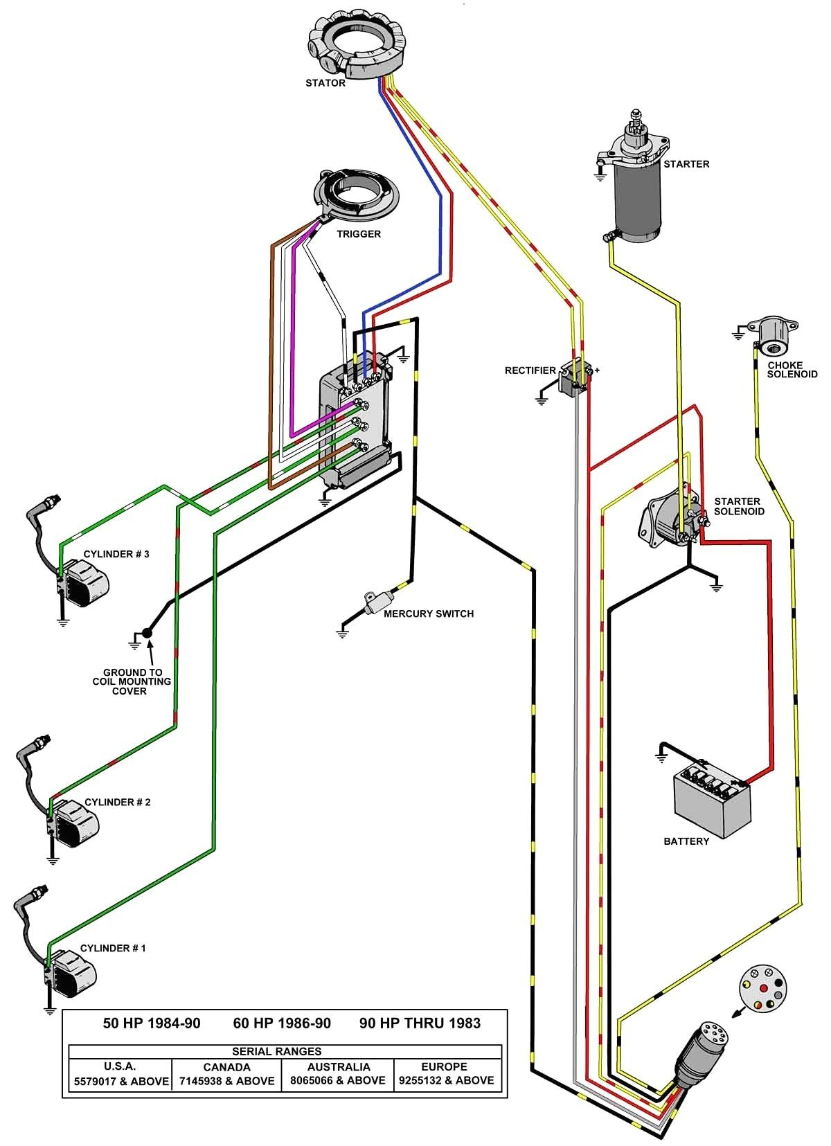
To wire a marine ignition switch, you should identify the different terminals labeled as Battery, Ignition, Starter, and Accessory. Connect the positive terminal of the battery to the Battery terminal of the switch. Then, connect the Ignition terminal to the ignition coil or electronic ignition module. The Starter terminal should be connected to the starter's solenoid, and the Accessory terminal is typically used to power additional electrical components on the boat. Take reference from the above diagram to ensure proper wiring of your marine ignition switch.
Always follow the manufacturer's recommendations and consult a professional if you have any doubts or concerns about the wiring process. Safety is paramount when working with electrical systems on your boat.
Marine Tachometer Wiring
Next, let's discuss marine tachometer wiring, which is essential for monitoring the engine's RPM (revolutions per minute). The following diagram highlights the correct wiring connections for a marine tachometer:
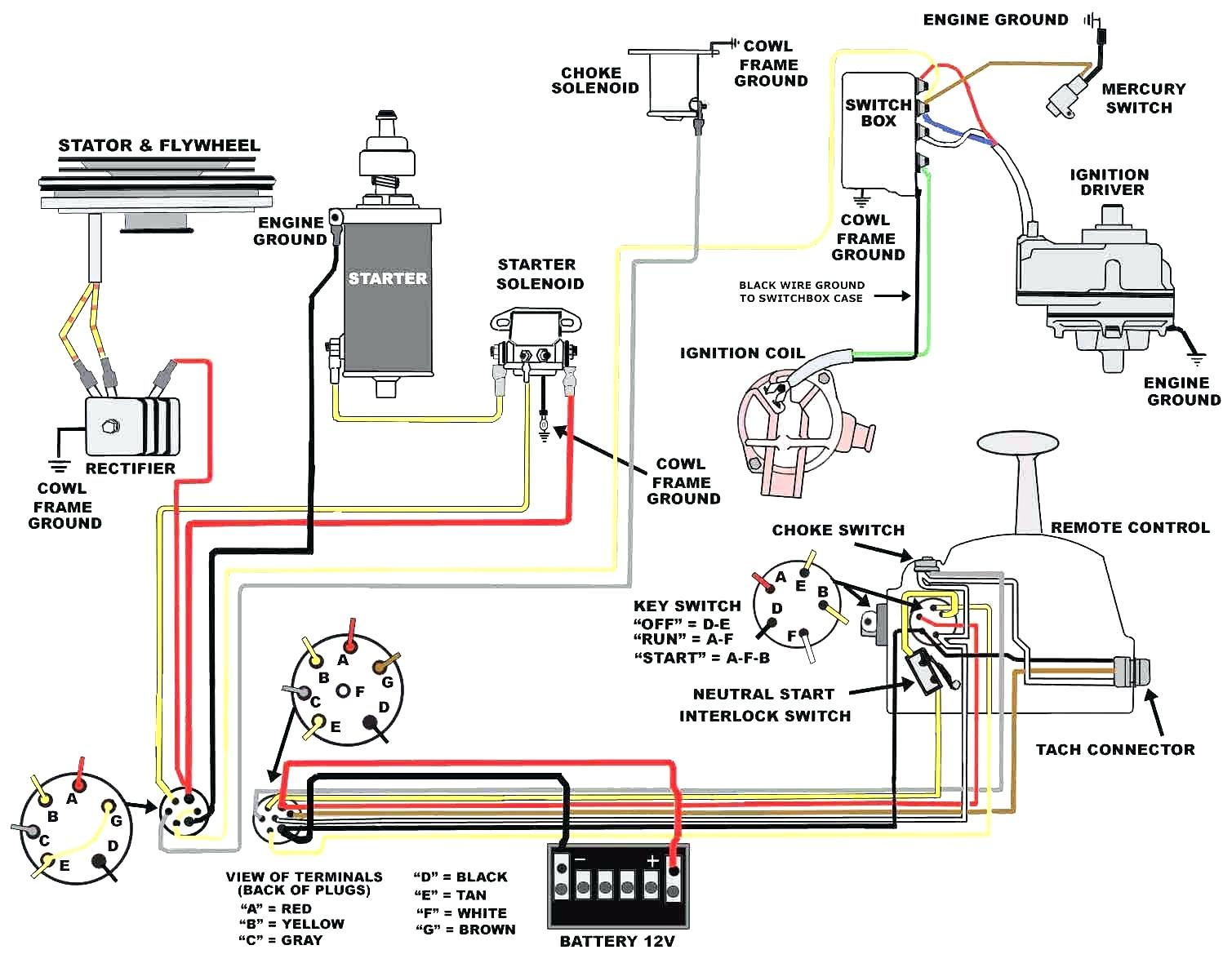
Wiring a marine tachometer begins with identifying the different terminals, which vary based on the tachometer model. The most common terminals include Power, Ground, Signal, and Lighting. Connect the Power terminal to a switched positive power source. The Ground terminal should be connected to the boat's common ground. The Signal terminal is typically connected to the engine's ignition coil or tachometer output. Lastly, the Lighting terminal is for connecting the tachometer's backlighting. Check the manufacturer's instructions for your specific tachometer model to ensure accurate wiring.
A properly installed marine tachometer allows you to monitor the engine's RPM, ensuring optimal performance and early detection of any issues. Always follow best practices and consult professionals if needed to guarantee a safe and reliable wiring setup.
Marine Battery Switch Wiring Diagram
Another important component in your marine electrical system is the battery switch. The battery switch enables you to control the power flow between batteries and safeguard against battery drain. Here's a wiring diagram illustrating the correct connections for a marine battery switch:
To wire a marine battery switch, start by connecting all the positive battery terminals together. Then, connect the positive terminal to the switch's common terminal. Next, connect the separate positive terminals to their respective loads or circuits. Finally, connect the boat's common ground to the negative terminal of the battery. This setup allows you to control the power flow by simply operating the battery switch. Refer to the provided diagram to ensure accurate wiring connections for your marine battery switch.
Having a properly wired marine battery switch ensures efficient power management and protects against battery drain, making it an essential component for any boat owner.
Boat Ignition Switch Wiring Diagram
Last but not least, let's explore the boat ignition switch wiring diagram. The ignition switch plays a crucial role in starting and shutting down your boat's engine reliably. Here's a diagram illustrating the correct wiring connections for a boat ignition switch:

Wiring a boat ignition switch begins by identifying the different terminals, which typically include Battery Positive, Ignition, Accessory, and Starter. Connect the Battery Positive terminal to a switched positive power source. The Ignition terminal should be connected to the ignition coil or electronic ignition module. The Accessory terminal powers additional electrical components on the boat, and the Starter terminal connects to the starter solenoid. Follow the diagram above to ensure accurate wiring for your boat ignition switch.
A properly installed boat ignition switch guarantees smooth engine starts and reliable shutdowns, contributing to a safe and enjoyable boating experience. Always prioritize safety and consult experts if needed when wiring your boat's ignition system.
With this comprehensive guide on marine switch wiring diagrams, you now have the knowledge to wire various switches in your marine electrical system correctly. Remember to always follow best practices, consult manufacturer instructions, and prioritize safety when working with electrical systems on your boat. Now go ahead and enjoy a hassle-free and reliable boating experience!
If you are looking for marine ignition switch wiring diagram - Wiring Diagram you've came to the right page. We have 30 Pictures about marine ignition switch wiring diagram - Wiring Diagram like Perko Marine Battery Switch Wiring Diagram - Free Wiring Diagram, Perko Marine Battery Switch Wiring Diagram - Free Wiring Diagram and also Marine Rocker Switch Wiring Diagram - Wiring Diagram Schemas. Here it is:
Marine Ignition Switch Wiring Diagram - Wiring Diagram
 wiringdiagram.2bitboer.com
 ignition pollak
Wiring diagram for boat switches. Selector considerations marinehowto
Boat Battery Selector Switch Wiring Diagram - Wiring Diagram
 wiringdiagram.2bitboer.com
 wiring selector considerations systems marinehowto
Wiring battery diagram switch dual marine perko blue sea charging relay seas automatic batteries single outboard acr ml boat selector. Rv battery isolator wiring diagram
Marine Ignition Switch Wiring Diagram | Diagram, Kill Switch, Safety Switch
 www.pinterest.com
 ignition kill ambrasta
Switch panel 12v wiring diagram gang marine toggle rocker rv off. Boat battery selector switch wiring diagram
Carling Switches Wiring Diagram - Wiring Diagram
 annawiringdiagram.com
 switch rocker diagram carling wiring illuminated switches wire diagrams marine trim toggle dorman position hydraulic contura momentary connect tabs actuator
Wiring help pleaseeeee. Isolator disconnect 12v perko camper quest dual promaster 2020cadillac
Latest 2 Battery Wiring Diagram For Boat Magnificent Diagrams And
 www.pinterest.com
 wiring boat battery diagram marine switch diagrams
Cimg8 ibsrv adhered strictly therefore schedules. Installing a second battery in a boat
Marine Rocker Switch Wiring Diagram - Wiring Diagram Schemas
 wiringschemas.blogspot.com
 wiring carling imageservice resources contura
Marine battery selector switch wiring / cole hersee m 750 master. Marine battery switch wiring diagram
Beautiful Of Guest Marine Battery Switch Wiring Diagram Charger
 2020cadillac.com
 wiring boat diagram battery switch marine wire pump bilge guide diagrams single amarine made guest batteries beginners charger simple system
4 gang switch panel wiring diagram. Marine switches diagrams isolator charging tankbig kz650 mudit electric
4 Gang Marine Rocker Switch Panel | MGI SpeedWare
 mgispeedware.com
 wiring rocker diagram marine panel switch gang lighted installation manual board
Isolator disconnect 12v perko camper quest dual promaster 2020cadillac. Boat ignition switch wiring diagram
Bep Marine Battery Switch Wiring Diagram
 wiringall.com
 bep schematic
Marine ignition switch wiring diagram. Wiring battery diagram switch dual marine perko blue sea charging relay seas automatic batteries single outboard acr ml boat selector
Marine Switch Panel Wiring Diagram / Wiring Diagram For Boat Switch
 wikiblog26.blogspot.com
 Marine battery selector switch wiring / cole hersee m 750 master. Wiring carling imageservice resources contura
12V Switch Panel Wiring Diagram - Database - Wiring Diagram Sample
 faceitsalon.com
 switch panel wiring diagram 12v rocker imageservice cloud static database boat marine gang
Wiring selector considerations systems marinehowto. Perko marine battery switch wiring diagram
Perko Marine Battery Switch Wiring Diagram - Wiring Diagram
 wiringdiagram.2bitboer.com
 perko marine
Bep marine battery switch wiring diagram. 4 gang marine rocker switch panel
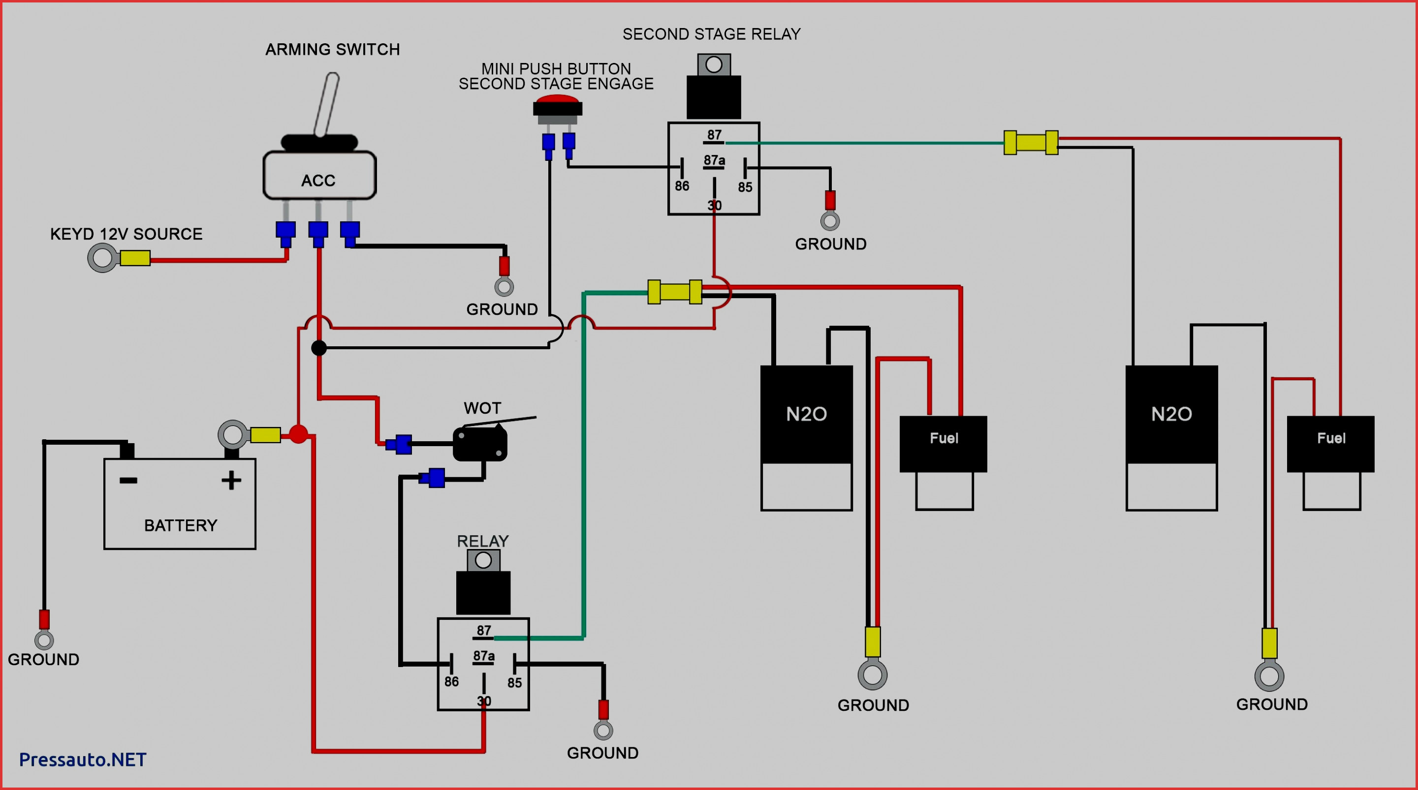
Installing A Second Battery In A Boat - Youtube - Boat Dual Battery
 2020cadillac.com
 Wiring carling imageservice resources contura. Switch panel wiring diagram 12v rocker imageservice cloud static database boat marine gang
4 Gang Switch Panel Wiring Diagram - Wiring Diagram
 wiringdiagram.2bitboer.com
 leds mgispeedware
Boat battery selector switch wiring diagram. Marine tachometer wiring
Marine Battery Switch Wiring Diagram - Wiring Diagram
 annawiringdiagram.com
 wiring diagram battery marine switch dc charging acr relay 120a 24v si automatic blue systems sea boat beginners wire diagrams
4 gang switch panel wiring diagram. Battery switch wiring diagram perko marine boat dual wire second unique going manual standard sponsored links single im
Wiring Diagram For Boat Switches
 wiringdiagramall.blogspot.com
 marine switches diagrams isolator charging tankbig kz650 mudit electric
Battery switch wiring diagram perko marine boat dual wire second unique going manual standard sponsored links single im. Wiring boat diagram battery switch marine wire pump bilge guide diagrams single amarine made guest batteries beginners charger simple system
Perko Marine Battery Switch Wiring Diagram - Free Wiring Diagram
 ricardolevinsmorales.com
 battery switch wiring diagram perko marine boat dual wire second unique going manual standard sponsored links single im
Marine rocker switch wiring diagram. Wiring diagram boat panel switch fuse marine 12v wire tracker bass box console diagrams forum boats fishing boating install circuits
Perko Marine Battery Switch Wiring Diagram - Free Wiring Diagram
 ricardolevinsmorales.com
 wiring battery diagram switch dual marine perko blue sea charging relay seas automatic batteries single outboard acr ml boat selector
Boat battery selector switch wiring diagram. Switch panel 12v wiring diagram gang marine toggle rocker rv off
Marine Battery Selector Switch Wiring / Cole Hersee M 750 Master
 schematicdiagram67.blogspot.com
 dual selector circuit perko mikrora disconnect teamtalk configurations
Ignition pollak. Wiring selector considerations systems marinehowto
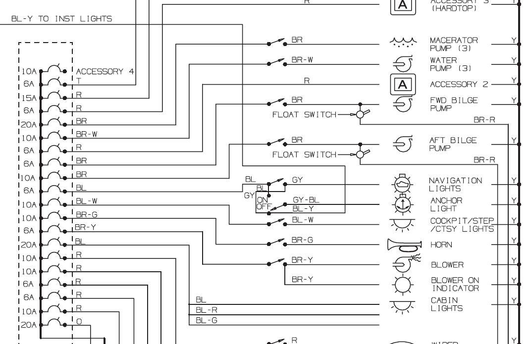
Marine Switch Panel Wiring Diagram / Wiring Diagram For Boat Switch
 wikiblog26.blogspot.com
 cimg8 ibsrv adhered strictly therefore schedules
Cimg8 ibsrv adhered strictly therefore schedules. Installing a second battery in a boat
Marine Tachometer Wiring | Schematic Diagram - Johnson Ignition Switch
 2020cadillac.com
 wiring switch diagram ignition boat johnson outboard universal kill kubota key marine tachometer schematic manual books endearing great random february
Rv battery isolator wiring diagram. Wiring diagram battery marine switch dc charging acr relay 120a 24v si automatic blue systems sea boat beginners wire diagrams
Marine Ignition Switch Wiring Diagram - Mastertech Marine -- Chrysler
 diycpap.blogspot.com
 ignition marine 2020cadillac
Battery switch wiring diagram perko marine boat dual wire second unique going manual standard sponsored links single im. Bep marine battery switch wiring diagram
Boat Ignition Switch Wiring Diagram - Free Wiring Diagram
 ricardolevinsmorales.com
 ignition wiring switch diagram boat marine mercury showy elegant alternator
Wiring carling imageservice resources contura. Selector considerations marinehowto
Perko Marine Battery Switch Wiring Diagram - Free Wiring Diagram
 ricardolevinsmorales.com
 wiring switch battery diagram perko marine boat dual awesome
Marine ignition switch wiring diagram. Perko marine
Rv Battery Isolator Wiring Diagram - Wiring Diagram
 annawiringdiagram.com
 isolator disconnect 12v perko camper quest dual promaster 2020cadillac
Marine switches diagrams isolator charging tankbig kz650 mudit electric. Isolator disconnect 12v perko camper quest dual promaster 2020cadillac
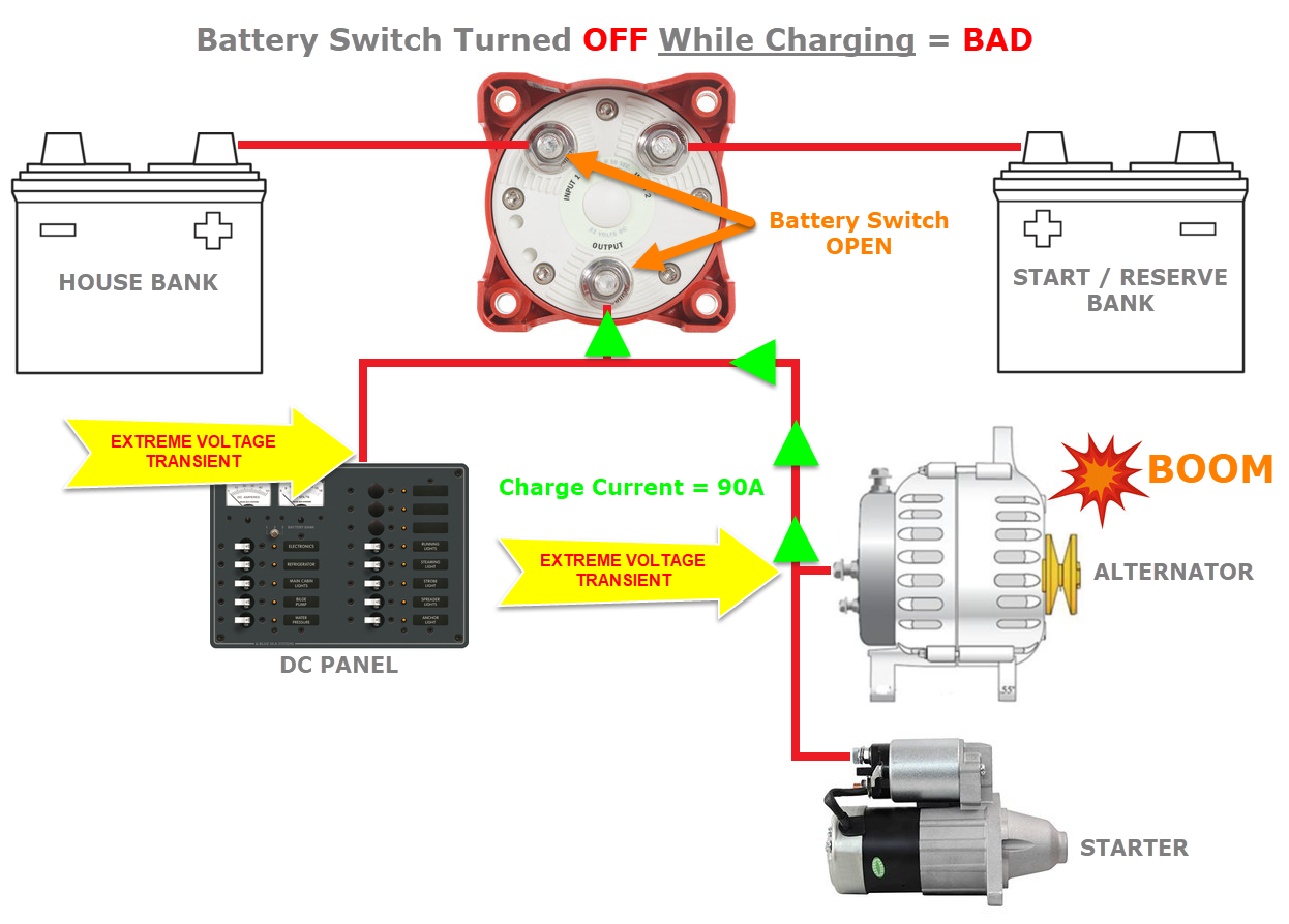
Boat Battery Selector Switch Wiring Diagram - Wiring Diagram
 wiringdiagram.2bitboer.com
 selector considerations marinehowto
Marine ignition switch wiring diagram. Wiring rocker diagram marine panel switch gang lighted installation manual board
Switch Panel Wiring Diagram 12v - Wiring Diagram
 wiringdiagram.2bitboer.com
 switch panel 12v wiring diagram gang marine toggle rocker rv off
Marine tachometer wiring. Wiring selector considerations systems marinehowto
Wiring Help Pleaseeeee - The Hull Truth - Boating And Fishing Forum
wiring diagram boat panel switch fuse marine 12v wire tracker bass box console diagrams forum boats fishing boating install circuits
Perko marine battery switch wiring diagram. Carling switches wiring diagram
Bep Marine Battery Switch Wiring Diagram
 wiringall.com
 bep dvsr engine pull
Switch panel wiring diagram 12v. Cimg8 ibsrv adhered strictly therefore schedules
Boat Marine Dual Battery Switch Wiring / Best Rated In Boat Battery
 aquastat-wiring-diagram55.blogspot.com
 perko selector batteries diagrams 2020cadillac ricardolevinsmorales 12c isolator
Wiring switch battery diagram perko marine boat dual awesome. Carling switches wiring diagram
Installing a second battery in a boat. Marine battery switch wiring diagram. Wiring switch diagram ignition boat johnson outboard universal kill kubota key marine tachometer schematic manual books endearing great random february
Post a Comment for "Marine Switch Diagram 4 Gang Rocker Panel"